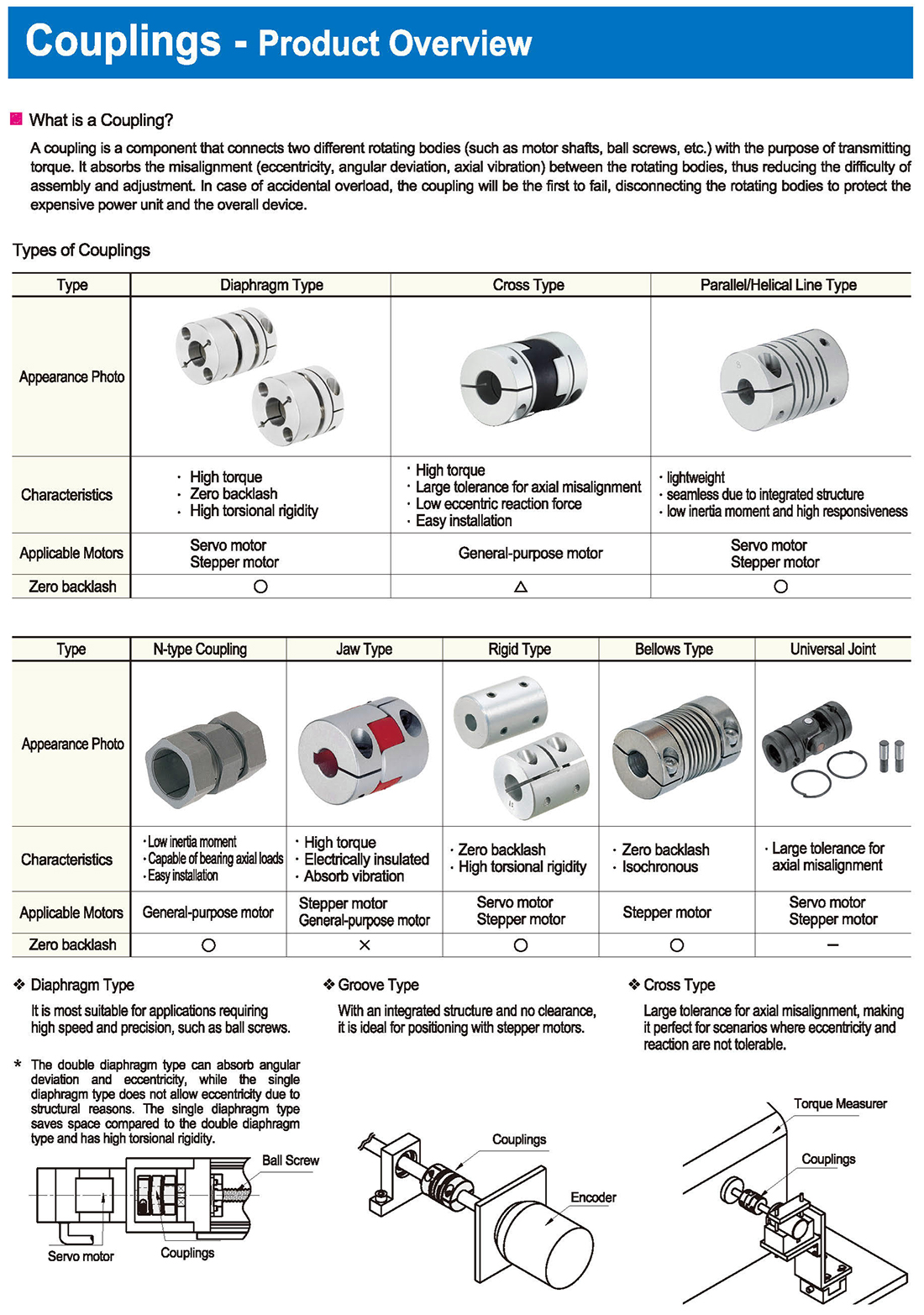
Kaplin Çeşitleri
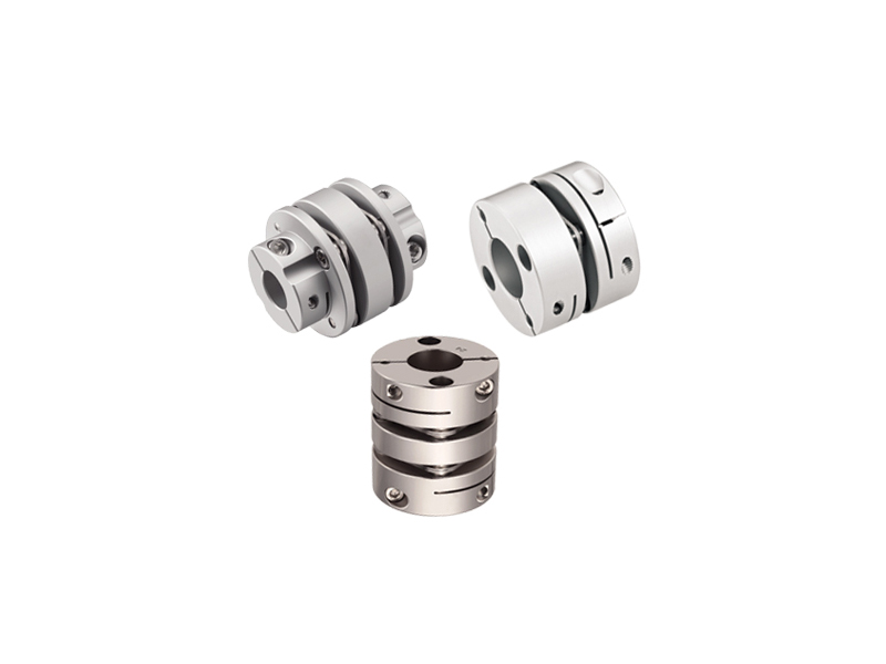
Tip: Diyafram Tipi, Çapraz Tip, Paralel / Helisel Çizgi Tipi
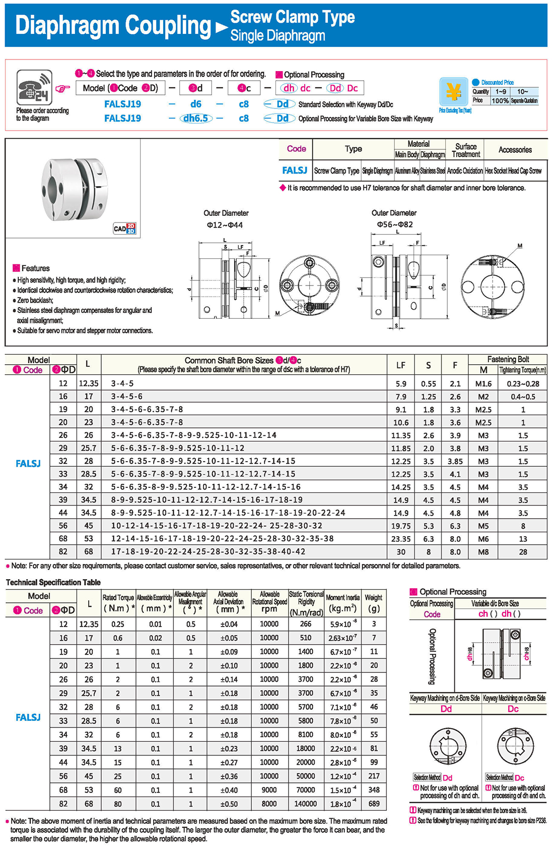
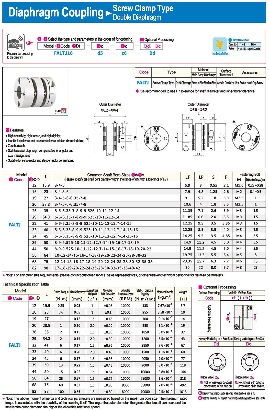
Bilyalı vidalar gibi yüksek hız ve hassasiyet gerektiren uygulamalar için en uygun olanıdır.
Oluk Tipi
Entegre bir yapıya sahip olması ve boşluk bırakmaması ile step motorlarla konumlandırma için idealdir.
Eksenel yanlış hizalamaya karşı büyük tolerans, eksantriklik ve reaksiyonun tolere edilemediği senaryolar için mükemmel hale getirir.
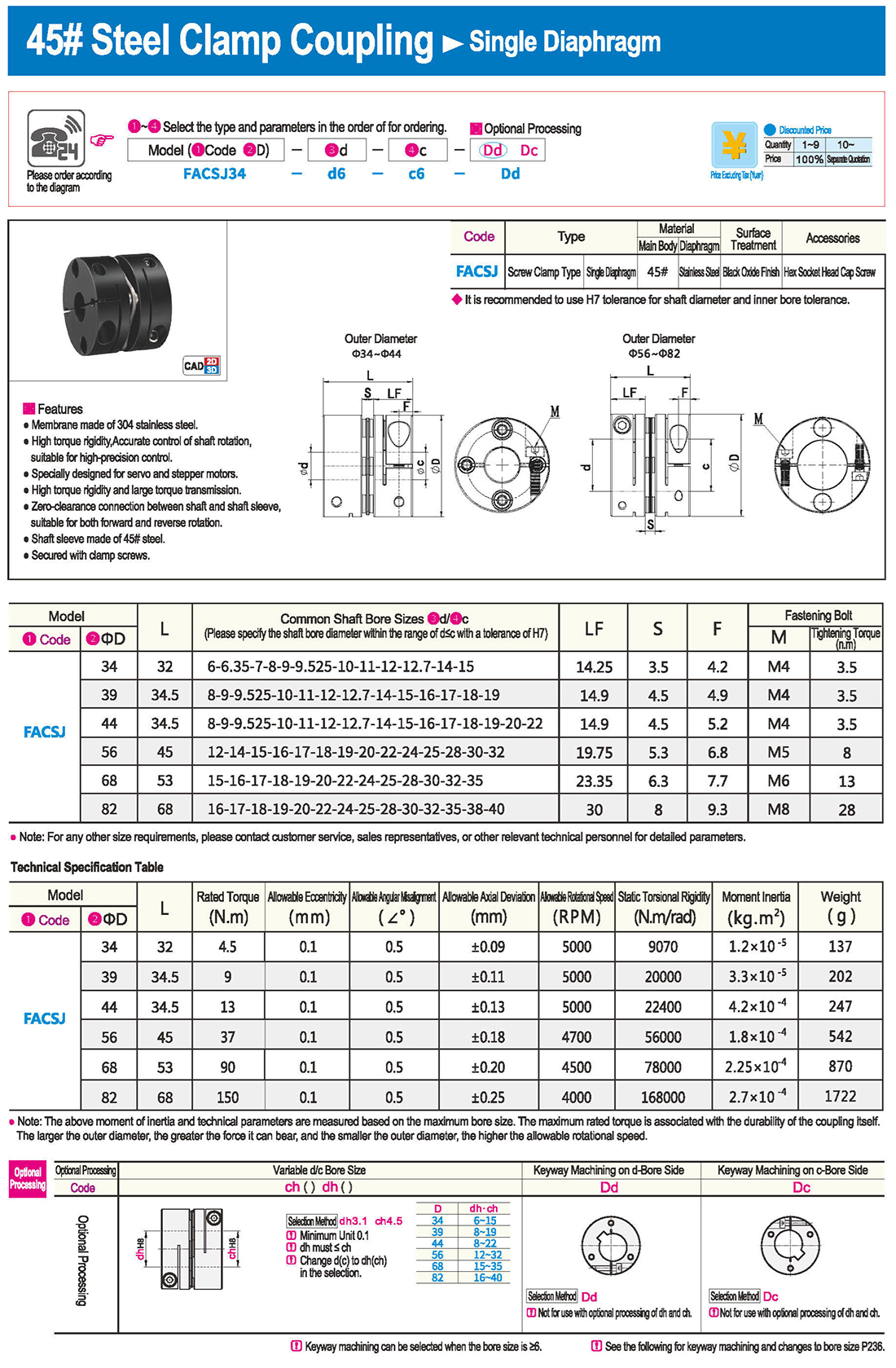
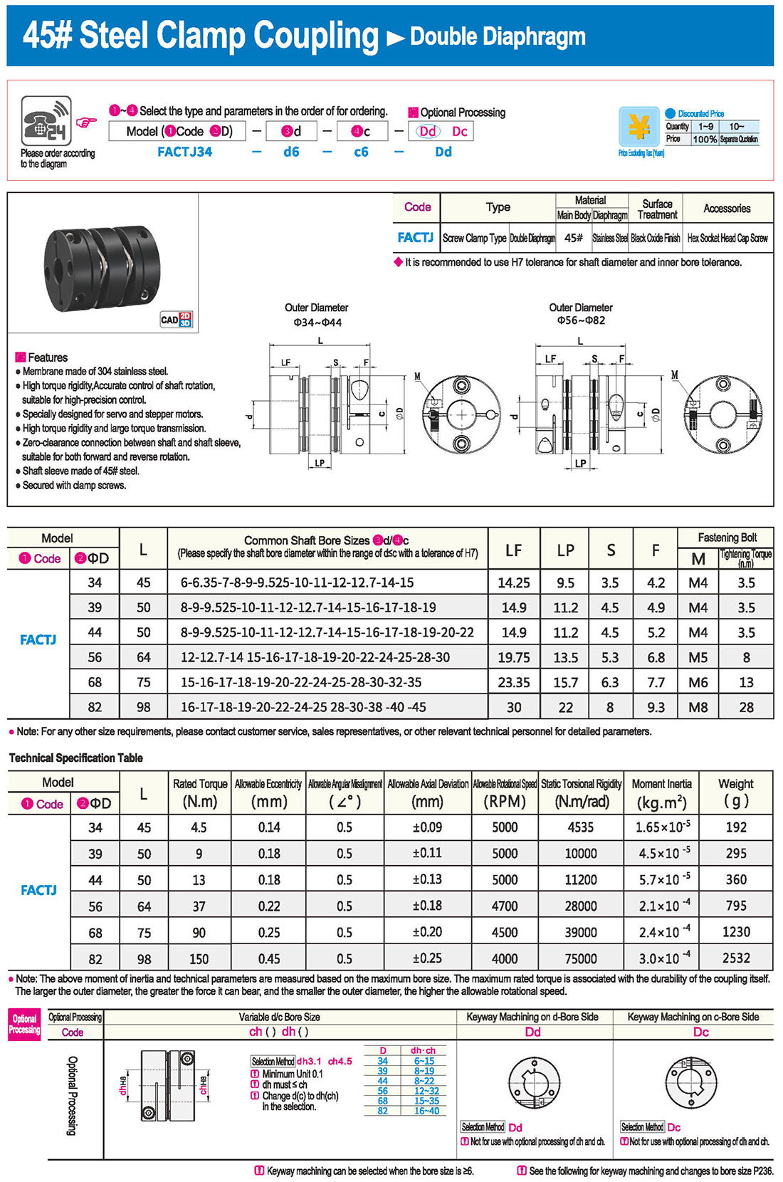
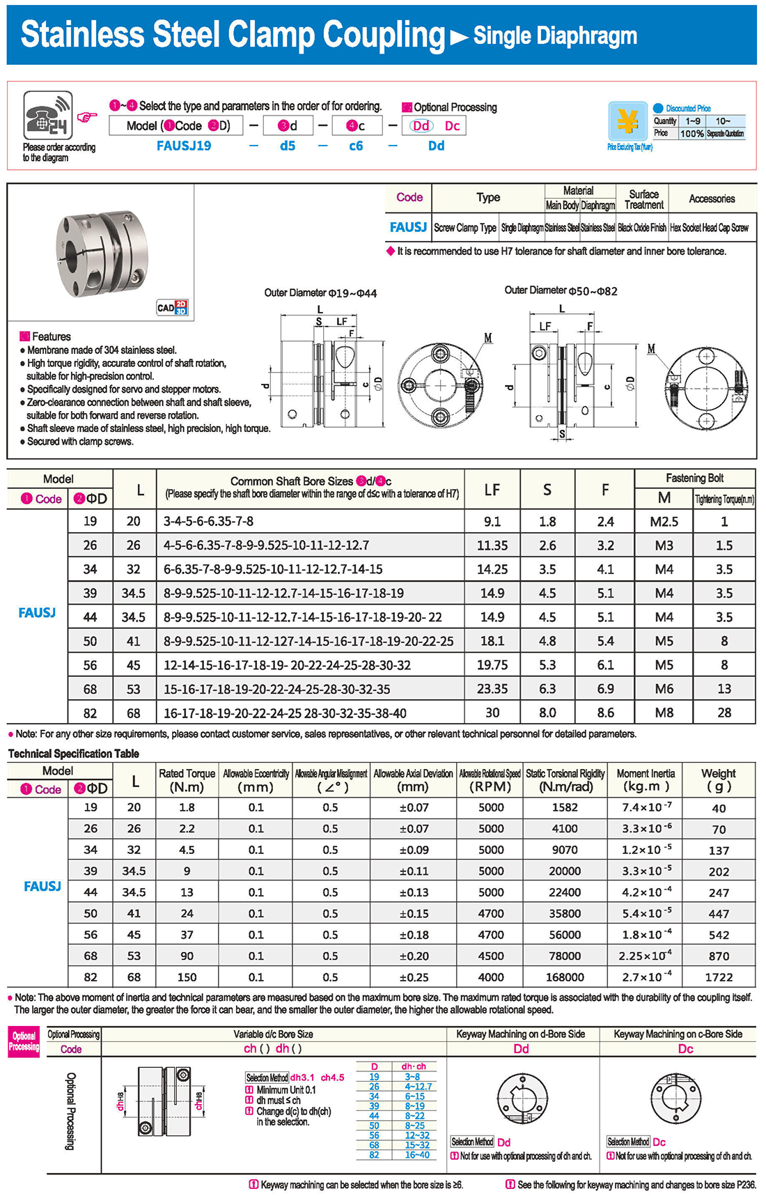
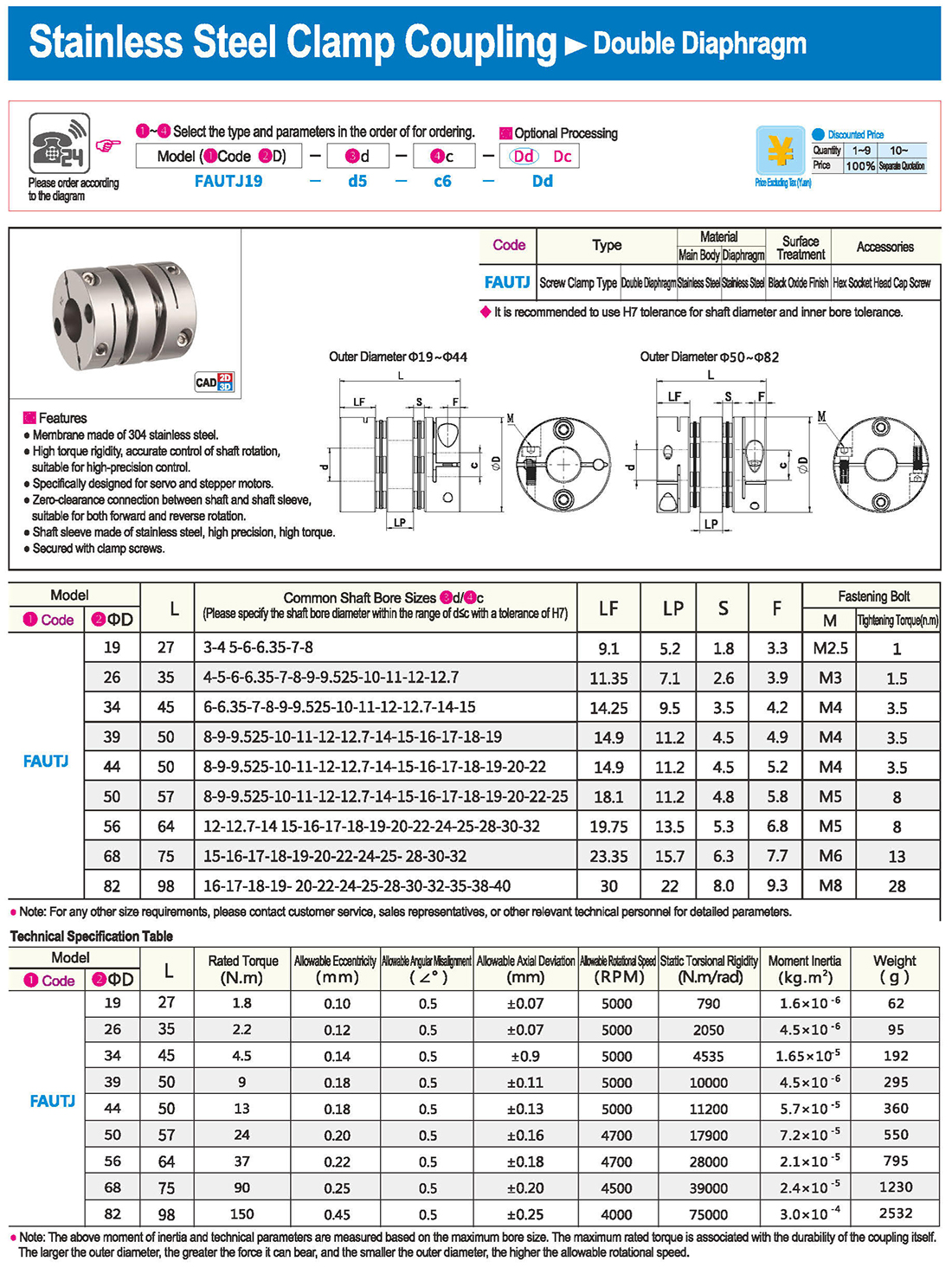
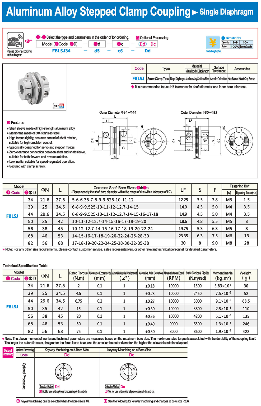
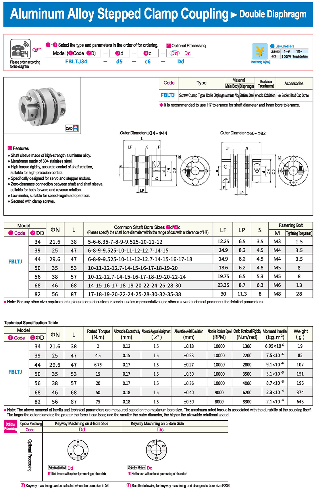
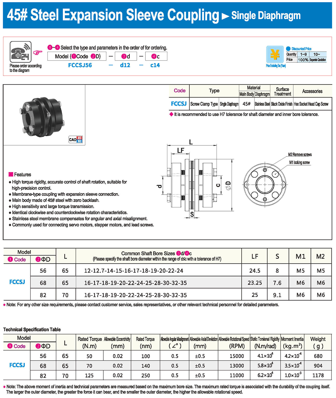
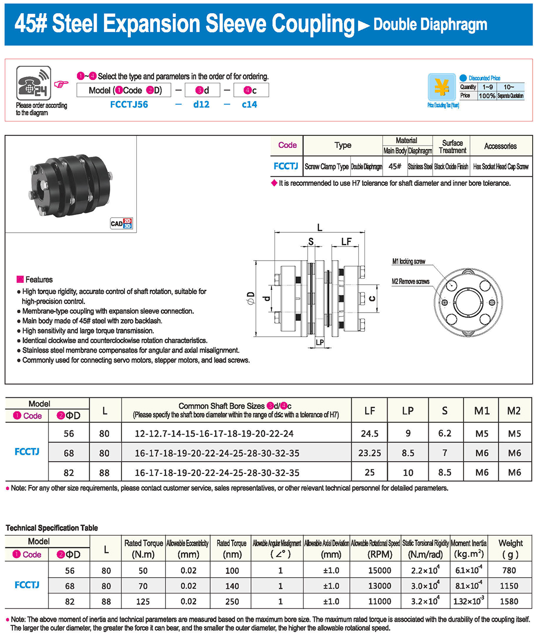
* Çift diyafram tipi açısal sapma ve eksantrikliği emebilirken, tek diyafram tipi yapısal nedenlerden dolayı eksantrikliğe izin vermez. Tek diyafram tipi, çift diyafram tipine göre yerden tasarruf sağlar ve yüksek burulma sertliğine sahiptir.
Enkoder ve Tork Ölçer
Motora göre seçim yaparken, lütfen motorun tipine ve uygulamasına göre uygun kaplin tipini seçin.
* Motor tipleri ve kaplin tiplerinin kombinasyonları aşağıda gösterilenlerle sınırlı değildir. Lütfen bir seçim yapmadan önce ilgili ürün sayfalarına bakın.
* Torka göre seçim yaparken lütfen 2. adımdan başlayın.
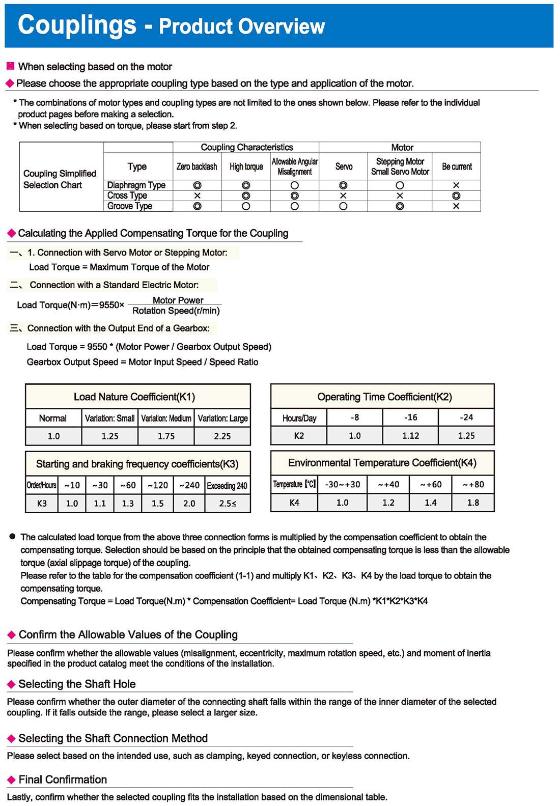
Coupling Simplified Selection Chart
Diaphragm Type Coupling Characteristics Allowable Angular Misalignment Motor Stepping Motor, Small Servo Motor
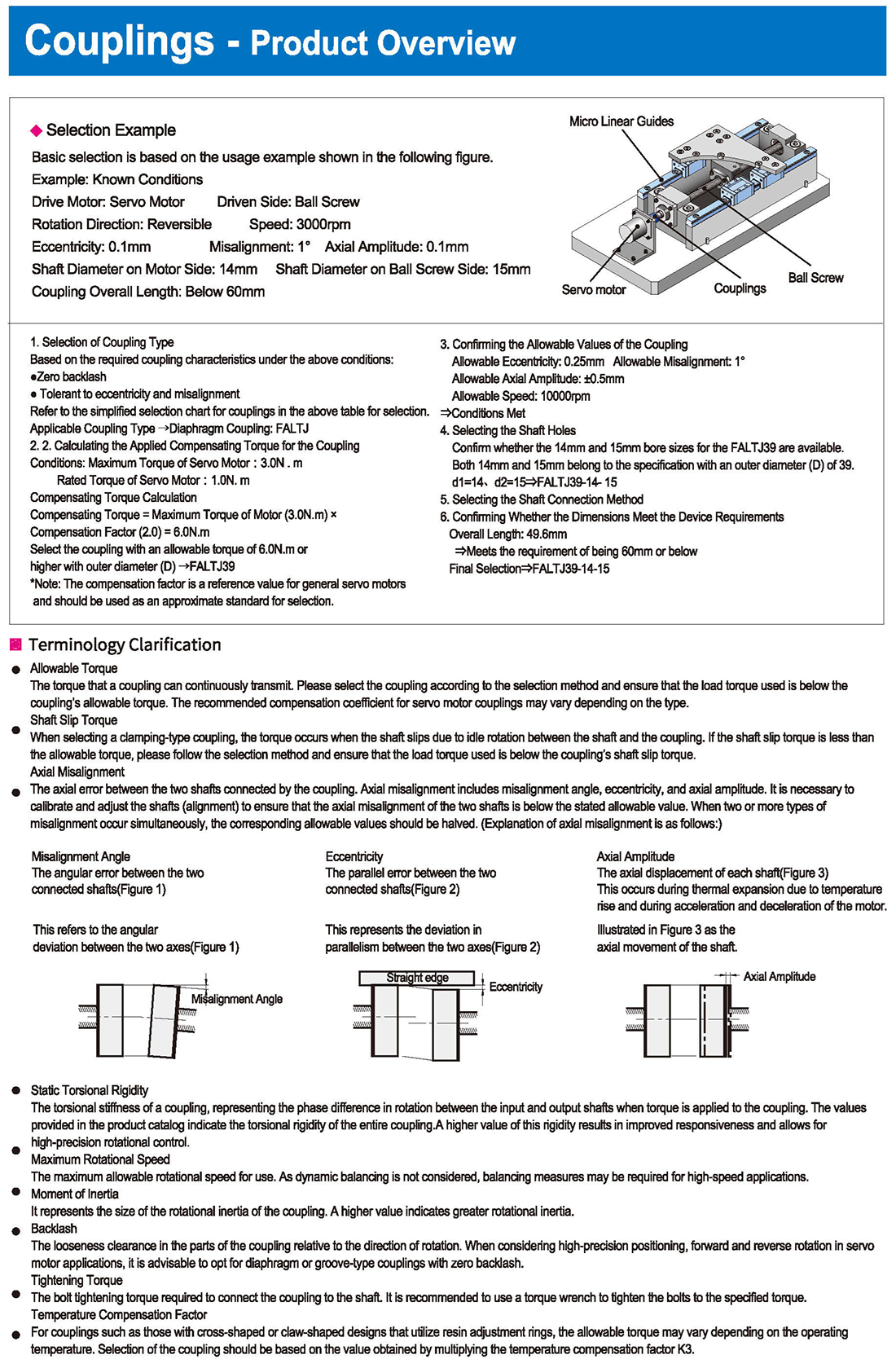
Calculating the Applied Compensating Torque for the Coupling
1. Connection with Servo Motor or Stepping Motor: Load Torque = Maximum Torque of the Motor
2. Connection with a Standard Electric Motor: Load Torque, Motor Power, Rotation Speed
3. Connection with the Output End of a Gearbox:
Load Torque = 9550 * (Motor Power / Gearbox Output Speed) Gearbox Output Speed = Motor Input Speed / Speed Ratio
Load Nature Coefficient, Operating Time Coefficient, Environmental Temperature Coefficient
Normal, Variation: Small, Medium, Large, Hours/Time, Exceeding, Temperature
The calculated load torque from the above three connection forms is multiplied by the compensation coefficient to obtain the compensating torque. Selection should be based on the principle that the obtained compensating torque is less than the allowable torque (axial slippage torque) of the coupling.
Please refer to the table for the compensation coefficient and multiply K4 by the load torque to obtain the compensating torque.
Compensating Torque = Load Torque * Compensation Coefficient = Load Torque
Confirm the Allowable Values of the Coupling
Please confirm whether the allowable values (misalignment, eccentricity, maximum rotation speed, etc.) and moment of inertia specified in the product catalog meet the conditions of the installation.
Selecting the Shaft Hole
Please confirm whether the outer diameter of the connecting shaft falls within the range of the inner diameter of the selected coupling. If it falls outside the range, please select a larger size.
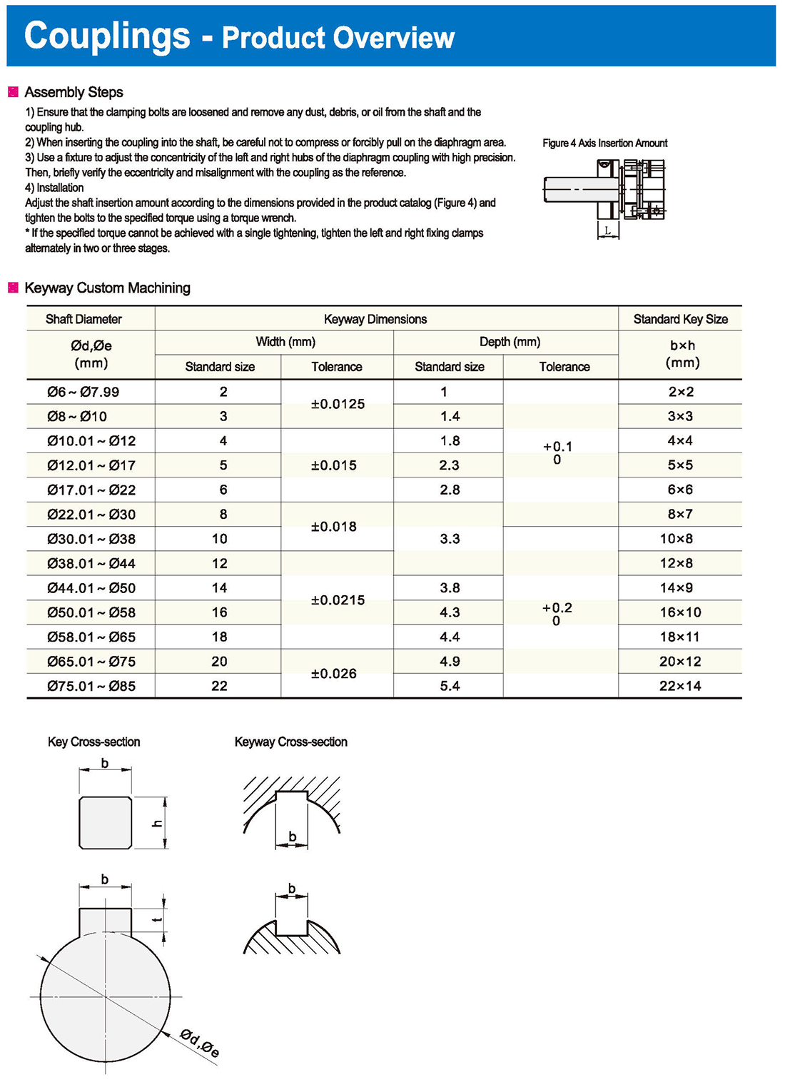
Selecting the Shaft Connection Method
Please select based on the intended use, such as clamping, keyed connection, or keyless connection.
Final Confirmation
Lastly, confirm whether the selected coupling fits the installation based on the dimensional table.


 İngilizce
 Rusça
Rusça İspanyolca
 İtalyanca
 Arapça
 Kore dili
 Almanca
 Japonca
 Vietnam dili
 Türkçe
 Giriş
Giriş Şartname Tablosu
 İndirmek


